2. First Steps
This chapter provides instructions for getting the RK3399-Q7 EVK running after opening the box.
2.1. Required Tools
- PZ1 (Pozidriv) screwdriver
2.2. Insert the Module
Insert the RK3399-Q7 module at a 30-degree angle into the connector in the base board. Once fully inserted , push it down until it rests on the standoffs and check alignment of the mounting holes.
Note
The module springs back into the 30-degree angle once released. This is expected, and alignment will be kept. The module will be secured into place together with the heatsink.
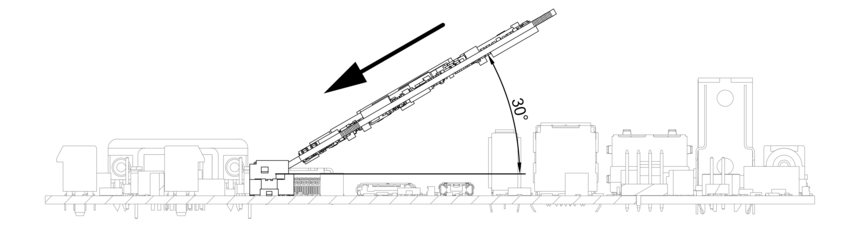
Module mounting
2.3. Mount the Heatsink
The heatsink has the thermal pad attached on the bottom. Peel off the red protective foil.
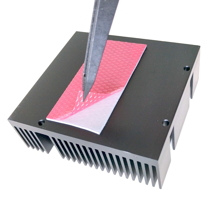
Thermal pad protective foil
Push the module down flat and place the heatsink spacer on the module with the smooth side facing up. Make sure the orientation is correct by checking alignment of the mounting holes. Place the heatsink on the spacer and screw it down gently using the four included M2.5 screws.
Heatsink mounting
2.4. Mount the Fan (optional)
The fan is only necessary in exceptionally high ambient temperatures. Under normal conditions, the RK3399-Q7 operates passively cooled.
Place the fan on the heatsink and clip it into place using the provided holder.
Connect the cable to the header labeled FAN on the baseboard.
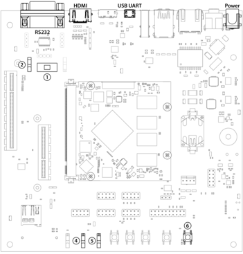
2.5. Power Up
The EVK modules comes preloaded with software that boots into a full desktop environment on the HDMI output. For bootloader configuration and Linux console the serial interface can be used. Connect either a Micro-USB or RS-232 cable to the corresponding port. Select the correct UART with UART selector slider (1). For Micro-USB the slider has to be in the right position to route the default console UART0 to the USB UART bridge. For RS-232 the slider has to be in the left position and the protocol slider (2) has to be in the RS-232 position.
Connect the power supply and verify the sliders are in the position Normal
Boot (4) and Normally Off (5). Press the Power Button (6) to power
the board. You will see the boot progress and later on a login prompt on the
serial interface. If a HDMI display is connected video output will follow
shortly after.