2. Using the EVK
2.1. About this Chapter
This chapter provides instructions for using the Evaluation Kit, such as booting and how to configure and use I/O peripheals (e.g. serial console, Ethernet).
2.2. Board Layout Overview
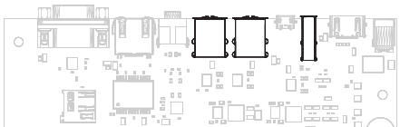
The board provides connectors for external I/O devices (top row in the image below), for data storage (top-left corner) and for internal connections (bottom row). Two means of supplying the board are provided (right row), as well as power control functionality, both on-board and extendable (via the CTRL connector) (bottom-left corner).
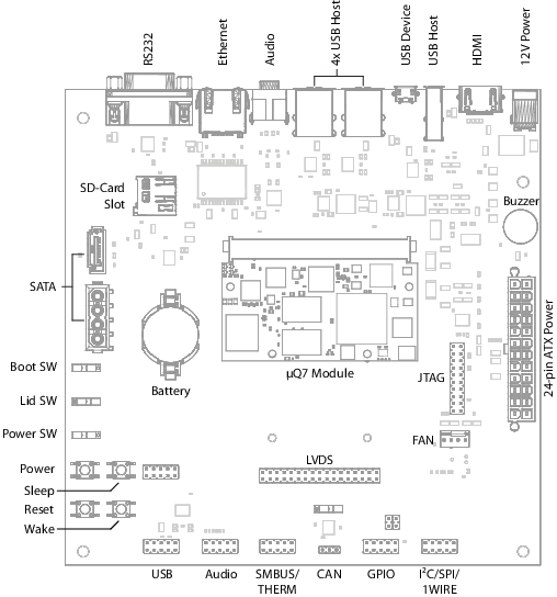
The base board for to A31 µQ7 module
2.3. Powering the Board
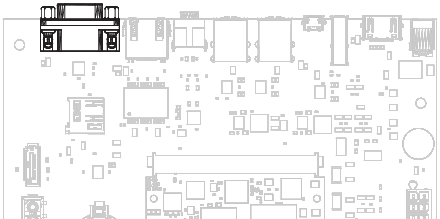
The baseboard can operate with a single 12V DC power supply.
12V power connector
Alternatively, the baseboard also provides an 24-pin ATX connector. The DC connector takes precendence if both are connected.
Note
When using ATX power, the A31 uQ7 module can only boot from the on-board eMMC memory as the ATX power supply does not supply the SD card while booting.
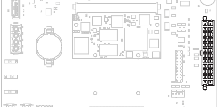
ATX power connector
Power can be controlled manually from the board using the power control buttons and switches, located on the left side of the board (see 2.2 Board Layout Overview).
2.3.1. Control Buttons
The control buttons provide Power, Reset, Sleep and Wake
functionality. The Power button can be disabled by setting the Power
Switch to Force On. This means the board will boot as soon as it receives
power.
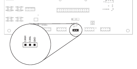
2.3.2. The Control Connector
The control connector provides an interface for accessing the control features of the board from outside (for example, from buttons placed conveniently on the front-panel of a case).
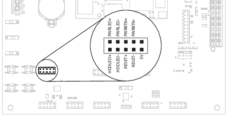
CTRL conncetor
The connector provides Power and Reset functionality, as well as pins
for the power LED and HDD activity LED.
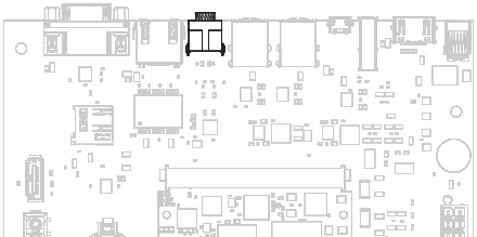
2.3.3. Connecting the CPU Fan
Operation in high environmental temperatures may require a CPU fan. The fan connector is located next to the bottom-right corner of the uQ7 expansion area (see board overview).
Note
The fan is only neccessary in high ambient temperatures. Under normal conditions, the A31 µQ7 operates passively cooled.
2.4. Booting from an SD Card
For information on preparing an SD card for the A31 µQ7 board, have a look at the Software Guide.
The SD card has to be inserted in the card slot on the baseboard (see image below).
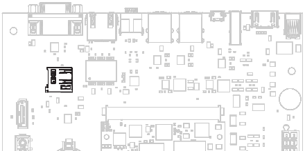
SD Card slot
On power up, A31 µQ7 module will normally try to boot from the internal flash. If this fails, it will attempt to boot from the SD card. If this fails as well, it will go into USB recovery mode.
The board can be forced to boot from the SD card by setting the slider labeled
SW2 on the board to the BIOS Disable position. This will tell the A31 µQ7 module
to skip booting from the internal flash and boot from the SD card.
2.5. Connecting to the Board
The A31 µQ7 module supports serial and network connections, local connected input devices and HDMI output. The following sections explain how to use them.
2.5.1. Connecting to the Board via RS-232
To connect via RS-232, plug the included USB-serial cable into the RS-232 connector on the base board and connect it to a USB port of your host.
Note
The USB-RS232 cable that comes bundled with the EVK works without installing additional drivers on Windows and Linux. Mac OS X users find the driver (PL2303) on the included USB flash drive.
RS-232 connector
Picocom can be used to connect via the serial line (considering the USB is connected to USB0 on the host machine):
picocom -b 115200 /dev/ttyUSB0
After successful system bootup, the login console appears on the terminal:
a31-uq7 login:
You can login as root with password root or as user user with password
user.
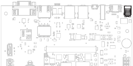
2.5.2. Connecting and Configuring Ethernet
The board has Gigabit Ethernet support. You can use either the on-board Ethernet adapter or one (or more) external USB Ethernet adapters.
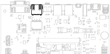
Ethernet port
2.5.2.1. Using DHCP
For convenience, the board can be configured to use DHCP (if not already done
when you have set up your filesystem). Open the file /etc/systemd/network/eth.network
in your editor of choice and add the following lines:
[Match]
Name=eth0
[Network]
DHCP=yes
And restart networking and check that the settings applied:
systemctl restart systemd-networkd
ifconfig
eth0      Link encap:Ethernet  HWaddr 02:51:09:06:88:8a
    inet addr:10.2.9.46  Bcast:10.2.255.255  Mask:255.255.0.0
    inet6 addr: fe80::51:9ff:fe06:888a/64 Scope:Link
          UP BROADCAST RUNNING MULTICAST  MTU:1500 Metric:1
          RX packets:329 errors:0 dropped:0 overruns:0 frame:0
 ....
If you plug in a USB adapter, it will be mapped to some other name
(eth1, for instance), so you have to change these lines accordingly (or add
new configuration lines in the eth.network file). To see all your network
adapters, use:
ifconfig -a
2.5.2.2. Using a Static IP
If you want a static IP instead of DHCP, use this configuration in
/etc/systemd/network/eth.network:
      [Match]
Name=eth0
[Network]
Address=192.168.0.7/24
Gateway=192.168.0.1
DNS=192.168.0.1
And restart the network daemon:
systemctl restart systemd-networkd
2.5.3. Connecting to the Board via SSH
If the network interface is running and there is a network cable plugged in, you should be able to connect to the board via ssh:
ssh root@xx.xx.xx.xx
root@xx.xx.xx.xx's password:
Where xx.xx.xx.xx is your board’s IP address.
Note that root login via ssh might be disabled (or only available with an ssh key,
not with a password). If you want to change this, open the sshd_config file
(/etc/ssh/sshd_config) and set PermitRootLogin to yes:
PermitRootLogin yes
Then restart the sshd service:
service ssh restart
2.5.4. Connecting USB Devices
USB keyboard, mouse and data sticks should work out of the box, just connect them to one of USB ports.
USB host ports
2.5.5. Connecting an HDMI Monitor
Before powering the board up, connect the monitor to the HDMI port. The monitor should be automatically discovered by U-Boot and you should see output both from U-Boot and from the Linux kernel. You will be able to use a mouse with a desktop environment if it is already installed. See the next chapter for how to install a desktop environment.
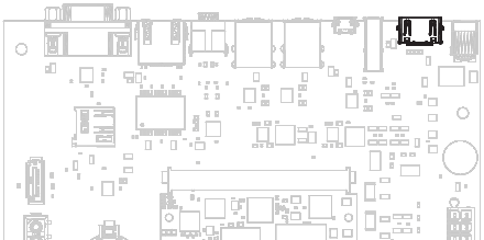
HDMI port
2.6. Using the External Interfaces
The board supports I2C, SPI and SATA, and provides a real time clock (RTC). This section explains how to use these capabilities.
2.6.1. Connecting an External USB Drive
To connect a USB drive, plug it into the desired USB port. The system should recognize the drive imediatelly. Check the kernel log to find the device name:
journalctl -k -10
You will be able to mount its partitions (assuming mapping to /dev/sdb1):
mkdir /mnt/pendrive
mount /dev/sdb1 /mnt/pendrive
cd /mnt/pendrive
ls
2.6.2. Connecting a SATA Drive
Plug the SATA drive into the SATA connector and power it from the power connector which is adjacent.
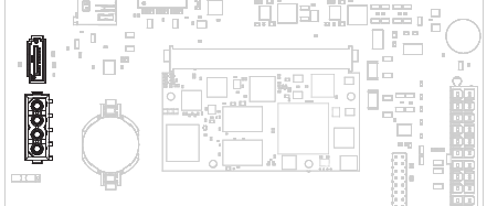
SATA data and power connectors
The system should recognise the drive imediatelly (just like a USB drive) and you will be able to mount its partitions:
mkdir /mnt/drive1
mount /dev/sda1 /mnt/drive1
cd /mnt/drive1
ls
In this example, it is assumed the drive will be mapped to /dev/sda1.
This is because the SD card is mapped to some device of the form
/dev/mmc1blk1, so the hard drive should be automatically assigned the name
sdax. Any new devices will be assigned names such as sdbx and so on, but
you can check this with journalctl:
journalctl -k -n 10
...
[417845.765419] sd 7:0:0:0: [sda] Attached SCSI removable disk
...
2.6.3. Setting the RTC
The RTC is read by the kernel on bootup and used to set the system clock.
To check the RTC value, use hwclock:
hwclock
Thu 30 Apr 2015 03:51:20 PM CEST  -0.826662 seconds
The RTC will be set automatically to the system clock on shutdown, so you can set the system clock using the date command and reboot to update the RTC:
date --set 2015-04-20
date --set 03:51:30
You can also update the RTC immediately, again with hwclock:
hwclock -v
You can set up an NTP client so the time will always be updated from the Internet. Install the client first:
apt-get install ntp
Feel free to change the /etc/ntp.conf file to use more local time sources
(change servers from pool.ntp.org to use a server from your country, such as
at.pool.ntp.org).
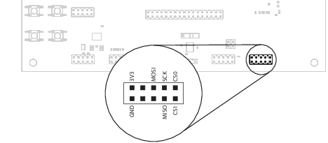
2.6.4. Using I2C and SPI
The first I2C (i2c-0) and SPI interfaces are both available on the base board (on the same connector). The following table contains the pinout (which is also printed on the board, next to the I2C/SPI/1WIRE connector):
| PIN | Function | Function | PIN |
|---|---|---|---|
| 1 | SPI_CS0# | SPI_CS1# | 10 |
| 2 | SPI_SCK | SPI_MISO | 9 |
| 3 | SPI_MOSI | 1WIRE | 8 |
| 4 | I2C_CLK | I2C_DATA | 7 |
| 5 | 3V3 | GND | 6 |
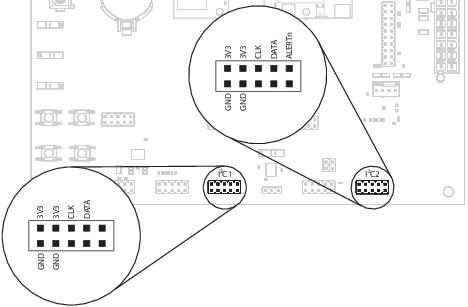
The second I2C (i2c-1) connector is located on the SMBUS/TERM connector on the baseboard (SMB_DAT and SMB_CLK pins):
| PIN | Function | Function | PIN |
|---|---|---|---|
| 1 | SMB_ALERT# | THERM# | 10 |
| 2 | SMB_DAT | NC | 9 |
| 3 | SMB_CLK | THERMTRIP# | 8 |
| 4 | 3V3 | GND | 7 |
| 5 | 3V3 | GND | 6 |
For I2C, there is the package i2c-tools available in Debian:
apt-get install i2c-tools
For more information on the package, have a look at the Debian page on i2c-tools.
2.6.4.3. I2C Example - Using a Touch Keyboard
This example uses the Atmel AT42QT2160 touch keyboard (see datasheet).
First, make sure the I2C is active in the device tree. In pangolin-linux edit the device tree source (arch/arm/boot/dts/sun6i-a31-pangolin.dts) and look for the entry for first I2C device (&i2c0) and set status to okay:
&i2c0 {
        pinctrl-names = "default";
        pinctrl-0 = <&i2c0_pins_a>;
        status = "okay";
};
Next, make sure the driver is installed via menuconfig:
make menuconfig
Navigate to Device Drivers -> Input device support -> Keyboards and check the ATMEL AT42QT2160 Touch Sensor Chip. We must recompile the kernel and deploy it to the SD card (see Software Guide).
2.6.5. Connecting the 1-Wire Bus
The 1-Wire connector is located in the same group with the first I2C (labeled
I2C/SPI/1WIRE.
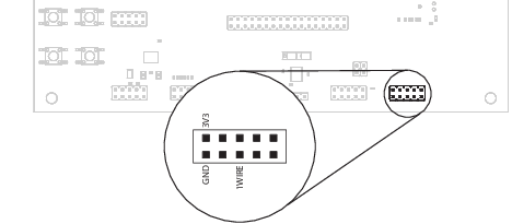
1-Wire header
2.6.6. Using the GPIOs
The GPIO interface is available on the base board and provides the following pins:
| Pin | Qseven signal | Qseven signal | Pin |
|---|---|---|---|
| 1 | GPIO0 | GPIO1 | 10 |
| 2 | GPIO2 | GPIO3 | 9 |
| 3 | GPIO4 | GPIO5 | 8 |
| 4 | GPIO7 | GPIO6 | 7 |
| 5 | 3V3 | GND | 6 |
The location on the board is displayed below:
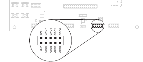
GPIO header
The GPIO numbers displayed printed on the board (and on the table above) are not the same as the ones used in Linux - i.e. /sys/class/gpio. You can find the Linux GPIO # in the following table:
| Qseven sginal | CPU pin | Linux GPIO # |
|---|---|---|
| GPIO0 | PG0 | 192 |
| GPIO1 | PG1 | 193 |
| GPIO2 | PG2 | 194 |
| GPIO3 | PG3 | 195 |
| GPIO4 | PG4 | 196 |
| GPIO5 | PG17 | 209 |
| GPIO6 | PG18 | 210 |
| GPIO7 | PG5 | 197 |
To calculate the GPIO # from the chip pin, use the following formula:
offset = block_number * 32 + index
Where:
- block_number: the alphabetincal index of the block name, minus 1
- index: the pin number within the block
For example, for GPIO_1 the pin is PG1. G has an alphabetical index of 7, so the block number is 6. Since the pin is PG1, the index is 1 so we add 1 to the offset:
offset = 32 * 6 + 1 = 193
To enable a GPIO, echo the GPIO number (“offset”) to export:
echo 192 > /sys/class/gpio/export
ls /sys/class/gpio/gpio192
cat /sys/class/gpio/gpio192/direction
in
cat /sys/class/gpio/gpio192/value
0
To set the direction to output, write out in the GPIO’s direction file:
echo out > /sys/class/gpio/gpio192/direction
echo 1 > /sys/class/gpio/gpio192/value
The GPIO will be set to a value of 1 (high at 3.3V).
2.6.7. Connecting Audio
The board provides two jack audio connectors for input and output.
Audio input/output port
Aditionally, an expansion connector for audio is available on the bottom row of the board:
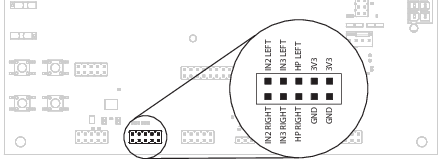
Connecting to the audio expansion connector
2.6.8. Connecting Additional USB Ports
The USB expansion connector is available on the bottom row of the board.
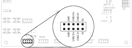
USB expansion header
2.6.9. Connecting the SMBUS/THERM Connector
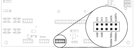
SMBUS/THERM header